Slot Online Bukan Jalan Pintas Kaya, Melainkan Hiburan
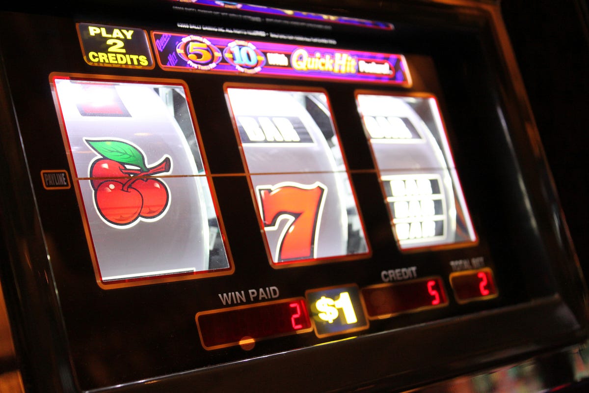
efxkits.us – Dalam beberapa tahun terakhir, slot online menjadi salah satu permainan kasino digital yang paling banyak diminati. Tampilan grafis…
efxkits.us – Dalam beberapa tahun terakhir, slot online menjadi salah satu permainan kasino digital yang paling banyak diminati. Tampilan grafis…
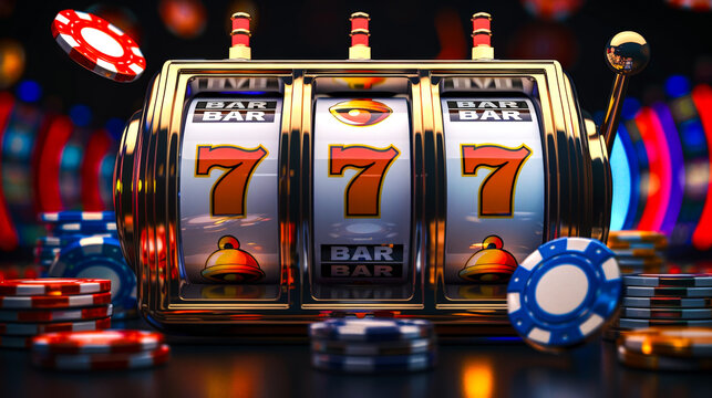
efxkits.us – Slot online saat ini menjadi salah satu permainan paling populer di dunia perjudian digital. Dari segi tampilan, variasi…
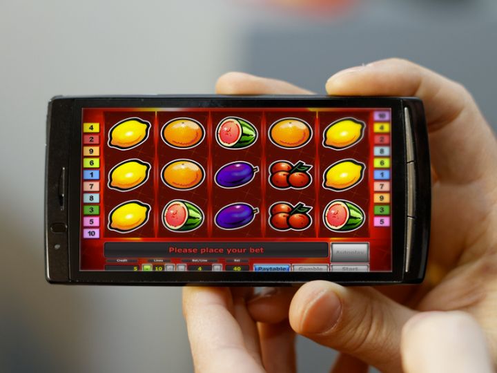
efxkits.us – Dalam dunia permainan slot online, berbagai fitur bonus terus bermunculan untuk menambah keseruan dan meningkatkan peluang menang para…
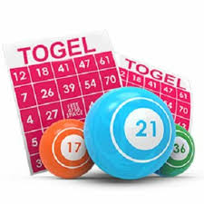
efxkits.us – Permainan tebak angka atau yang lebih dikenal dengan Togel telah lama menjadi bagian dari budaya perjudian di berbagai…
efxkits.us – Slot online saat ini menjadi salah satu permainan paling diminati dalam dunia perjudian digital. Kombinasi antara visual memukau,…
efxkits.us – Togel adalah permainan yang menggabungkan keberuntungan dan strategi, menawarkan keseruan serta hiburan bagi banyak pemain di seluruh dunia.…
efxkits.us – Slot online menjadi salah satu permainan kasino digital paling populer karena kemudahannya dan peluang menang yang menarik. Namun,…
efxkits.us – Judi bola online adalah aktivitas yang semakin populer di kalangan penggemar olahraga. Namun, agar dapat menikmati pengalaman ini…
efxkits.us – Kasino online telah menjadi pilihan populer bagi banyak pemain yang ingin merasakan sensasi perjudian tanpa harus pergi ke…
efxkits.us – Rtp slot rajacuan69 merupakan sebuah istilah yang digunakan pada permainan slot, yang memiliki fungsi untuk memberitahu pemain seberapa…